Daily problems and issues that are hard to resolve about SSMS,SSRS,SSIS,SSAS,DTS,Agent, Optimization, Administration, Always On, Clustering, Point in Time recovery and more...
Search This Blog & Web
Sunday, January 11, 2015
Thursday, May 29, 2014
SQL Server Storage Enigne: Update Statement Life Cycle Summary
From the previous blog
SQL Server Storage Engine: Select Statement life cycle summary
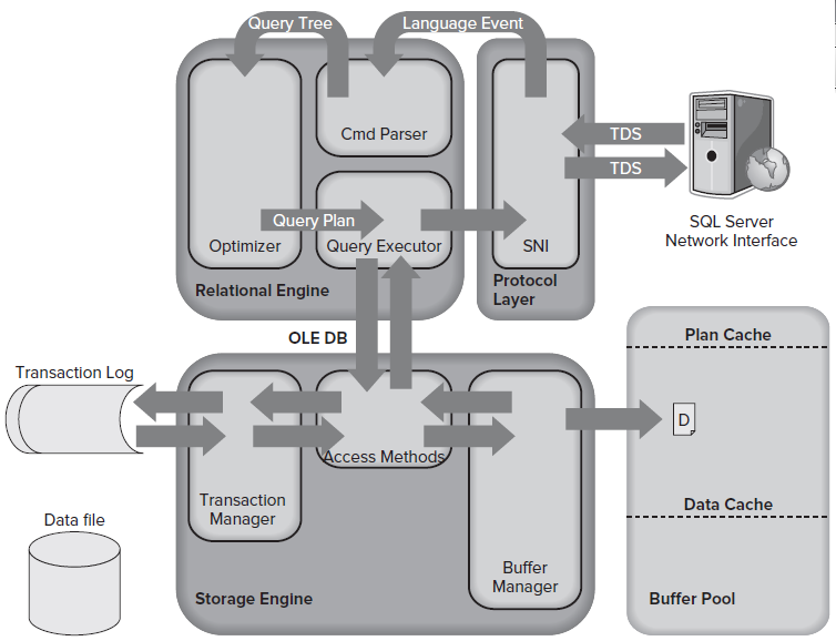
Now we will start learning about What happens in database engine when an update statement will be issued. Same structure follows as with select statement for SNI, and Rational Engine and Access Method part, as we can see till Point 5 from the previous post and we can also see this in attached picture.
At the point of Access Method as in Select statement It goes to Buffer Manager here it goes to Transaction Manager.
SQL Server Storage Engine: Select Statement life cycle summary
Now we will start learning about What happens in database engine when an update statement will be issued. Same structure follows as with select statement for SNI, and Rational Engine and Access Method part, as we can see till Point 5 from the previous post and we can also see this in attached picture.
At the point of Access Method as in Select statement It goes to Buffer Manager here it goes to Transaction Manager.
Transaction Manager
Write-ahead logging (WAL): The Access Methods code requests that the changes it wants to
make are logged, and the Log Manager writes the changes to the transaction log.
Writing to the transaction log is the only part of a data modification
transaction that always needs a physical write to disk because SQL Server
depends on being able to reread that change in the event of system failure.
What’s actually stored in the transaction log is details of the
page changes that occurred as the result of a modification statement. This is
all that SQL Server needs in order to undo any change.
The actual data modification can only be performed when confirmation
is received that the operation has been physically written to the transaction
log. This is why transaction log performance is so crucial.
Once confirmation is received by the Access Methods, it passes
the modification request on to the Buffer Manager to complete.
Buffer Manager
The page that needs to be modified is already in cache, the page
is modified in the cache, and confirmation is sent back to Access Methods and
ultimately to the client.
The key point here is that the UPDATE statement has changed the data in the data cache,
not in the actual
database file on disk.
This is done for performance reasons, and the page is now what’s
called a dirty page because it’s different in memory from what’s on disk.
These dirty pages will be written back to the database file
periodically whenever the free buffer list is low or a checkpoint occurs.
Tuesday, May 27, 2014
SQL Server Storage Enigne: SELECT Statement Life Cycle Summary
Figure shows the whole life cycle of a SELECT query, described here:
1. The SQL Server Network Interface (SNI) on the client established a connection to the SNI on the SQL Server using a network protocol such as TCP/IP. It then created a connection to a TDS endpoint over the TCP/IP connection and sent the SELECT statement to SQL Server as a TDS (Tabular data stream) message.
2. The SNI on the SQL Server unpacked the TDS message, read the SELECT statement, and passed a “SQL Command” to the Command Parser.
3. The Command Parser checked the plan cache in the buffer pool for an existing, usable query plan that matched the statement received. When it didn’t find one, it created a query tree based on the SELECT statement and passed it to the Optimizer to generate a query plan.
4. The Optimizer generated a “zero cost” or “trivial” plan in the pre-optimization phase because the statement was so simple. The query plan created was then passed to the Query Executor for execution.
Next steps involve in making execution plan will be
Phase 0 — During this phase the optimizer looks at nested loop joins and won’t consider parallel operators.The optimizer will stop here if the cost of the plan it has found is < 0.2. A plan generated at this phase is known as a "transaction processing", or TP, plan.
Phase 1 — it uses subset of the possible optimization rules and looks for common patterns for which it already has a plan. The optimizer will stop here if the cost of the plan it has found is < 1.0. Plans generated in this phase are called "quick" plans.
Phase 2 — This final phase is where the optimizer pulls out all the stops and is able to use all of its optimization rules. It also looks at parallelism and indexed views (if you’re running Enterprise Edition). Plans created in this phase have an optimization level of “Full.”
5. At execution time, the Query Executor determined that data needed to be read to complete the query plan so it passed the request to the Access Methods in the Storage Engine via an OLE DB interface.
6. The Access Methods needed to read a page from the database to complete the request from the Query Executor and asked the Buffer Manager to provision the data page.
7. The Buffer Manager checked the data cache to see if it already had the page in cache. It wasn’t in cache so it pulled the page from disk, put it in cache, and passed it back to the Access Methods.
8. Finally, the Access Methods passed the result set back to the Relational Engine to send to the client.
Subscribe to:
Posts (Atom)